 |
|
 10-09-2008, 10:30 PM
|
#1
|
|
|
Ultimate Fusion F8 Maintenance/Breakdown/Info Thread
The Ultimate Fusion F8 Breakdown and Info Thread
While I have pictures of only the Fusion in this thread, the F8 is built so similarly, that nearly everything is this thread can be used for the F8 as well.
( From the Dangerous Power Website)
Quote:
From design to conception, the Fusion Paintball Marker by Dangerous Power aims to achieve the highest level of performance at any price.
If you’ve tried shooting one, you will agree that this mission has been accomplished! Out of the box, the Fusion rivals the performance of other ‘high-end’ markers that are double or even triple the cost, leaving the competition wondering how quality can come at such affordability. Fusion owners also Have confidence in knowing that their purchase is backed by highly trained technical support staffs, read to provide unparalleled excellence in customer service should the need arise.
The limited comes pre-installed with a color kit, the patented RAPS (Rapid Air Pressurizing System) ASA system, and can easily be identified by a special serial number located beneath the trigger guard.
All Limited Fusion carry LIMITED LIFETIME WARRANTY.
|
Fusion
Weights: 2.49lbs
Length: 19.6 inches
Height: 9.32
Operating Pressure: 250 psi
F8
Weight: 1.89 lbs
Length: 19 inches
Height: 7.4 Inches
Operating Pressure 200 psi
As always, DP customer service is some of the best in the industry. If you have any problem with any DP marker, don’t hesitate to call. DP is more than willing to help answer any question or address any problem, large or small.
DP Customer Service Team
Customer Service - 10am to 6pm PST
(909) 869-7800 | info@dangerouspower.com
Service and Parts - 10am to 6pm PST
(909) 869-8801 | service@dangerouspower.com
The Fusion is a Fasor marker design which basically just means that the Ram returns with a spring instead of with pneumatics/air. Similar markers designs are the Spyder and Legend markers.
Shooting out of box better than markers several times its price, the fusion needs NO upgrades, and it can work with both Low Pressure and High Pressure tanks.
**DO NOT USE CO2**
While there are so many lubes out on the market today, DP recommends the use of Dow-55 lube on the entire marker. I agree with this and you will notice that even though I have Dow-33 in the Picture of the workplace. I don’t use dow33 on this marker except on the internal solenoid piston, which is my preference. Any type of lube will work, however to avoid leaks and extend life of O-rings, the use of a swelling type lube is the recommended.
What to do after each day of play?
Even though I have listed all the info in all the sections below, I’m sure there are quite a few people that are not going to want to read through the entire thing to find out what needs to be done after each day of play. So here’s the skinny.
Wipe all paint off of marker. (Exterior, interior, bolt, eyes, barrel,)
Clean and relube ram assembly (See Section Below)
Every 15,000 – 20,000 shots clean, inspect, relube HPR and LPR. Sooner if they become inconsistent. (See Sections Below)
Links to Sections:
How to Crono your Fusion
Fusion VS F8
Breakdown N Maintenance of the Fusion Bolt and Ram
Disassembly of the HPR
Breakdown and Maintenance of the Fusion LPR
Fusion RAPS
Separation of the Frame and Body on the Fusion
Breakdown of the Fusion Solenoid
Removing the Fusion Valve
Removing the Fusion Trigger
Useful Knowledge
Other Fusion Links:
Register Your Marker
Official Dangerous Power Fusion Manual
Official Dangerous Power F8 Manual
Common Fusion Problems and Solutions
O-ring Troubleshooting
O-ring Sizes (Thanks to Rottensquad07)
F8 Completely Disassembled (Thanks to xYodax)
Fusion Aftermarket Parts List (Thanks to xYodax)
How to Crono your Fusion by fds (Thanks to fds/lucky4143)
How to flip your valve (Thanks to IntenseImage)
Solenoid Maintenance Video (Thanks to IntenseImage)
Last edited by meMYSELFnI : 11-25-2008 at 10:10 PM.
|

|

|
 Sponsored Links
|
Remove Advertisement
|
|
Advertisement
|
|
|
10-09-2008, 10:30 PM
|
#2
|
|
|
How To Crono Your Fusion:
There are 2 main ways that most Fusion owners use.
First method is the easiest.
Bottom out both regulators. (screw the velocity screws clockwise until they stop/shut off air)
Unscrew your velocity screw on the LPR out until the C-clip stops it.
Air it up and adjust HPR until you have desired feet per second using a chronograph.
Second method gives best efficiency softest on paint.
Bottom out both regulators like in the first method.
Air up the marker and adjust the HPR velocity screw watching closely at the gauge until it reaches 250 psi.
Unscrew the LPR velocity screw slowly while you click the trigger until the marker completely cycles.
Add an additional ¼ - ½ turn on the LPR velocity screw to ensure that the marker has enough pressure at high rates of fire to not give you drop off. If you get drop off just adjust the LPR velocity screw out another ¼ - ½ turn.
While the Fusion has an LPR, many users dont use it. Many argue that the LPR has such minute adjustments that it doesnt make that big of a difference.
While I agree to an extent, I do like the ability to FINE TUNE my marker. You will see in the breakdown section that I have changed a couple stock parts that have allowed me to lower my OP (operating pressure) and lowered the perceived recoil when shooting.
Its hurt my efficiency slightly, but not by much.
The F8 is cronod by simply adjusting the HPR velocity screw.
Last edited by meMYSELFnI : 02-06-2009 at 10:22 PM.
|
|
|
|
|
10-09-2008, 10:30 PM
|
#3
|
|
|
Fusion vs F8
The differences between the Fusion and the F8 are size, weight, and the F8 doesn’t have an LPR.
The breakdown guide can be used for F8 owners as well as Fusion owners. While both look quite differently, both operate nearly identical. With just a few cosmetic differences that shave off the size and weight of the F8, the F8 has been completely overhauled on the exterior. Don’t let the size full you. The F8 still has a very generous area for you big guys with huge hands in the trigger area.
The F8 is easier to maintain than the fusion because of the lack of the LPR.
Neither of them needs any tools to do regular maintenance. Lube the valve pin and ram regularly and just wipe off the bolt after your days of play. It’s recommended that you clean and lube your HPR and LPR (Fusion) every 15,000 – 20,000 balls.
Additionally, it is wise to make cleaning your eyes and dents, part of regular maintenance to ensure performance and reliability.
Since both operate with interchangeable parts, both perform nearly identical with cosmetics, size, and weight being the largest differences.
Some parts that have been upgraded on the F8 are the solenoid and regulator.
The F8 solenoid has been “improved for extended battery life and pressure tolerance, redesigned pressure regulator for improved reliability…” From DP’s website.
The parts kit that DP offers for the fusion is also the same that is offered for the F8.
 Fusion/F8 Kit Includes:
1 Solenoid (upgraded – uses 30% Less Battery Power than stock Fusion Solenoid)
Complete O-ring Kit
3 Solenoid Pistons to Rebuild Solenoid
Replacement Shims for the HPR
Replacement Shims for the LPR
2 Replacement HPR Regulator Seat
2 Replacement HPR Velocity Screws
Replacement C-clips for both the LPR and HPR
Replacement Springs for the Dents
Replacement Ball Dents
1 Pair of Eye Wires W/Eyes
Every screw on the entire marker
Things not included:
Valve
Valve Pin
Valve’s internal O-ring/Cup Seal O-ring
Solenoid mounting to body O-rings (1mm x 2mm)
AFTERMARET PARTS FOR THE FUSION AND F8
Aftermarket Products for the Fusion and F8
THEBETTERONE's http://ruthlesspaintball.com (AKA TBO) Trigger for Fusion & F8
Review links of TBO trigger
TheNforcer Review of F8 Trigger
Dsiturbed989s' review of TBOs' F8 Trigger
Border's Review - Behold--TBO's F7 Trigger! Installed and Reviewed w/ Pictures!
Last edited by meMYSELFnI : 01-02-2018 at 12:32 PM.
|
|
|
|
|
10-09-2008, 10:30 PM
|
#4
|
|
|
Breakdown and Maintenance of the Fusion Bolt and Ram
Having the right tools and clean work area, make doing maintenance just that much more easy. Notice that I have a complete O-ring kit. This is the first thing anyone with a fusion should buy second only to lube. If you play a lot, you will realize that the right tools make the job easier. I have a strapwrench, a good set of allen wrenches, pick set, teflon tape, and a screw driver with multiple heads. In my toolbox I also have bought replacement parts that could have problems. If I didn’t play as much as I do, these wouldn’t be necessary. Still an extra regulator seat would be very useful to add to your toolkit. If you buy one from DP a pair of cheap C-clip pliers make changing out the velocity screw MUCH easier. I have a pair that cost less than $5 from Harbor Freight.

After each day of play, it is important to clean and maintain your bolt and ram on the Fusion.
No tools are needed to take out the bolt or ram. However, you will need a rag to clean off old lube and lube to relube. Again, Dow55 is recommended.
Step #1 Pull the bolt pin up and slide the bolt out the back.
 Step #2
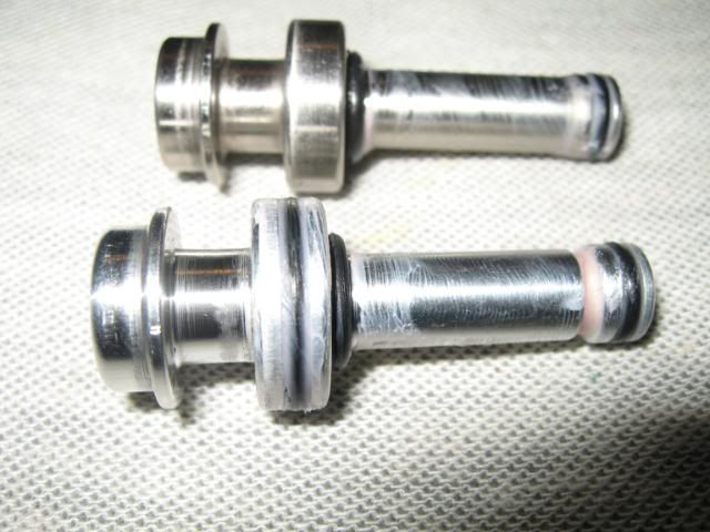
 Turn the ram cap ¼ turn counterclockwise and pull out the ram assembly.
I have the Eigenram (extra O-ring)and the stock ram pictured below.
 Step #3
 Clean all lube off the ram, and then reapply new lube to the ram's sleeve (black with 2 O-rings) and the tail section of the ram. Basically, just apply lube to all O-rings.

Put everything back together in the same order you took it out.
Remember just a ¼ turn to lock the ram in place.
If your ram cap is loose you may need to tighten the set screw for the ball bearing that secures your ram to the body. If the screw does come loose, it would be a good idea to apply blue loctite to the threads before replacing to ensure it doesn't happen again.

Here is what the retaining bearing assembly looks like.

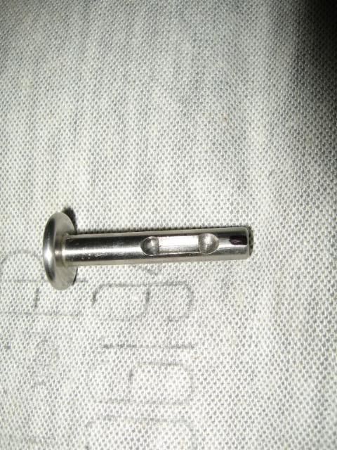
If you install an Eiganram you may need to sand your stock pin to fit into the ram. You will only have to sand a very small spot on the bottom of your ram. Look at the picture. The black spot indicates where you need to sand. You will only need to take off a very small amount of material. I would suggest that you sand it flat and check the fit often by inserting the pin in the ram. Notice that the black mark is directly below the slot.
Last edited by meMYSELFnI : 10-09-2008 at 10:36 PM.
|
|
|
|
|
10-09-2008, 10:30 PM
|
#5
|
|
|
Disassembly of the Fusion HPR (High Pressure Regulator)
Servicing of the regulators is recommended by DP every 15,000 – 20,000 shots.
Remove macroline and air source before servicing the Fusion’s HPR.
Here are the tools needed:
Strap wrench
1/4 allen wrench
3/8 allen wrench
(Substitute 3/8 allen wrench for a 1/4" and 1/8" allen wrenches which are included with new purchases)
Dow55
Rag
Step #1 Loosen the HPR by turning it counterclockwise by hand or strap wrench. If you don’t have a strap wrench, a wet towel or even a computer mouse pad will give you a better grip when unscrewing this by hand. (Thanks xluben for the suggestions)
 Step #2
 If you can’t remove the top of the HPR by hand, you can use either a 3/8” allen wrench (as shown)to loosen it. This allen wrench is not supplied with the Fusion and will have to be purchased separately. An alternative is to use the strap wrench, wet towel, or even a computer mouse pad to help you removed the HPR with.

Here’s a little trick. Use the 1/4 allen wrench in combination with 1/8 allen wrench to loosen the top portion of the HPR. Simply put them side by side and use the same way as the 3/8 allen wrench.
 Step #3
 Using the 1/4” allen wrench, screw the velocity screw clockwise until it stops. This will raise the piston and make it easier to remove.
Holding the bottom half of the HPR upside down, gently tap the assembly on a flat surface until the piston falls free.
Step #4 Once the piston is out the assembly, it should look like this, but with the shims on the piston. Clean off all O-rings and wipe all surfaces clean. Replace any damaged O-rings and lube these O-rings.

Here’s a close up of the shim stack order. There are 8 shims in the HPR. Some Fusions came with a thin metal washer that rests against the piston. You can see mine has one in the picture above. This isn’t needed, but I keep mine in just because it came with the Fusion.
 Step #5
 There are 4 O-rings that need to be lubed occasionally on the HPR assembly.
2 of the O-rings you can see in the piston picture above. The other 2 O-rings that need to be lubed are here.

There is one last O-ring on the HPR that very rarely, if ever, needs to be serviced. This O-ring is on the velocity screw and is only able to be serviced if you remove the C-clip. You can see in the background that I have a pair of C-clip pliers, but I didn’t remove that screw because it’s still a pain.

Even thought that this isn’t apart of the HPR it’s pretty close. This is the vertical ASA (Air Source Adapter). There is one screw and one O-ring on this ASA. This O-ring rarely leaks, but if you get a leak in this area, at least you now know a possible cause.
Unscrew the internal screw with the ¼ inch allen wrench. This is what the assembly looks like disassembled.

 Tips n Tricks Tips n Tricks
**If you don’t like having to use a strap wrench or allen wrenches every time you need to clean your HPR, simply put a small amount of lube on the threads to prevent the threads from binding. Any thick lube would be fine for this application, although some will last longer than others.
*This is not necessary to do, but if you’re going to store your marker for an extended period of time. A very small amount of oil can be applied to the shims and then wiped off, so you have only a very thin layer on the shims. If you apply too much the shims can stick to one another, so just a small amount. The coating on the shims should prevent any moisture from corroding the metal shims, but it’s just an added protection.
Last edited by meMYSELFnI : 10-09-2008 at 10:36 PM.
|
|
|
|
|
10-09-2008, 10:31 PM
|
#6
|
|
|
Breakdown and maintenance of the LPR
The LPR, like the HPR rarely need to be serviced DP recommends that it be cleaned and lubed every 15,000 20,000 shots.
Tools needed:
¼ inch allen wrench
Flathead screwdriver
Lube
Rag
Step #1 Unscrew the LPR from the body counterclockwise. If its too difficult to grip the cap to unscrew, use the ¼ inch allen wrench to unscrew the velocity screw until it hits the c-clip. Once the screw hits the clip the screw will start to turn the entire LPR.
 Step #2
 After you have removed the LPR, remove the spring and poppit and set them aside. You will notice I have a different spring on the poppit  . Ive made some changes to the stock parts in order to further reduce my operating pressure.  Step #3
 Unscrew the flathead screw counterclockwise.
 Step #4
 Remove the screw, internal piston, and shims. Pay close attention to the shim stack order. There are 10 shims in all in the LPR. I also have pictured the velocity screw. Just like the HPR velocity screw it will nearly never need to be removed unless there is a problem.

Here is a top view so you can better see the LPR regulator seat.
 Step #5
 Clean all old lube from all O-rings. Relube all the O-rings very lightly with Dow 55.
This is how everything goes together. There is one O-ring that I failed to get a picture of. There is a small O-ring inside the LPR body that the small end of the piston slips though. This little O-ring can shift when putting the piston back into the LPR body if not put in straight. If this happens, itll case a leak. (Thanks xluben/DPServiceBen)
 Step #6
 Clean all lube off the outside of the LPR. I have some cheap tank O-rings on there now, that's why some are orange.

Relube with Dow 55

Put a small amount of lube on the valve pin O-ring and spherical part that contacts the valve, before putting it back together.
Last edited by meMYSELFnI : 02-06-2009 at 10:36 PM.
|
|
|
|
|
10-09-2008, 10:31 PM
|
#7
|
|
|
Disassembly of the Dangerous Power R.A.P.S. (Rapid Air Pressurizing System)
It’s entirely up to you to remove the RAPS from the rail or not. It’s not necessary if you just need to lube the piston or if you’re troubleshooting a leak.
Tools Needed:
3/32 allen wrench
5/64 allen wrench
Dow55
Step #1 If you would like to take off the RAPS from the rail use a 3/32 allen wrench to loosen the set screw. You shouldn’t need to remove the screw completely to get the RAPS off.
Step #2 Unscrew the screw securing the lever, spring, and piston to the RAPS using a 5/64 allen wrench.
 Step#3
 This is the internals of the RAPS. The piston, with the 2 O-rings on it, need to be lubed with dow55 or similar swelling lube.
These 2 O-rings are the cause of most leaks associated with the RAPS. Usually you just have to lube the O-rings, but if they show any signs of wear, replace them. Lube them with any lube you have on hand, swelling lubes work better. If you lube with Dow55 and you get a leak, it’s most likely because the lube has worn off and you may just need to relube them.

All Lubed and ready to be put back together.
Tips n Tricks
*The threaded hole on the side of the RAPS shouldn’t be messed with, unless you’re mounting a gauge. If you get a leak from that spot, Teflon or Blue Loctite should fix it. If you use Teflon tape make sure that it’s only on the threads of the screw.
*A small amount of lube on the threads where the tank screws in will help ease screwing the tank in and out. Apply it with your finger to either the tank threads or the internal RAPS threads. Don’t use oil.
*Always completely degas your marker prior to trying to remove the tank. After flipping the lever up, shoot a few times w/eyes off to get the rest of the air out of your marker. This will ensure that no pressure is still pressing against the tank, and will keep both the RAPS and tank threads in good condition.
*Here’s something to save you some grief with putting you’re micro lines into the elbows.
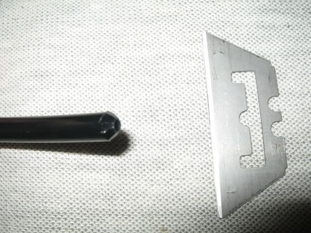
Taper/round the end of the macro fitting slightly. In the picture I just cut it with a razor blade. It makes inserting the macro much easier and holds just as well as leaving it at a 90* angle.
Last edited by meMYSELFnI : 02-06-2009 at 10:44 PM.
|
|
|
|
|
10-09-2008, 10:31 PM
|
#8
|
|
|
Separation of the Frame from Body on the Fusion
If you need to service the solenoid, remove the valve, install a rendition magnetic trigger, troubleshoot a leak, or you just want to see how what the inside of the marker looks like, this is your section.
Although it is recommended whenever you service anything on your marker to remove the air from the marker, you can separate the frame from body and then apply air, to troubleshoot a leak. Most of the time separating the frame to find a leak is not necessary. However, there are a couple screws that I will show you that could leak. These are the air passage screws that shouldn’t ever leak or be touched unless they are leaking. Refer to the “Useful Knowledge of the Fusion and F8” section.
The first and safest way to start is to remove any balls from the breach and air source. Make sure that after you remove the air source that you eliminate any air that might still be in the marker by shooting without the eyes on and air source removed.
Step #1 I like to remove the eye covers and eyes from the body. This allows me to inspect the eyes and remove any paint from them and clean the ball dents. If you prefer, you can just remove the connector from the board.

In this second photo I would like to mention that I have super glued my springs to the eye covers. They have never come off and I never have to worry about loosing them. This is a very useful trick that anyone with any Dangerous Power marker should do.  Step #2
 Once you have removed the eyes from the body, either by removing the connector or disassembling the eyes on the body. It’s time to remove the solenoid connector.
Open up the left grip to access the connector for the solenoid. If you have disconnected the eye's connector, you obviously already have this step done.

The solenoid connector is on the top right. Don’t pull on the wires to disconnect. Use a pair of small pliers if you can’t do it with your fingers like me. This picture shows a simple way to adjust your modes on the board. I have a little cheat sheet on the inside of the grip which is very convenient so I don’t have to memorize the modes. I have included this picture in the “Useful Knowledge” post.
 Step #3
 Now it’s time to LOOSEN the rear and front hidden screws. There is no need to remove these screws. Use your 3/32 allen wrench to loosen them.
  Step #4
 Slide the trigger frame to the rear of the body and you should be able to separate them easily.

To put back together just reverse the steps. Make sure that the eye and solenoid wires are not pinched between the body and frame when placing them back together.
Last edited by meMYSELFnI : 10-14-2008 at 10:04 PM.
|
|
|
|
|
10-09-2008, 10:31 PM
|
#9
|
|
|
Breakdown of the Fusion Solenoid
The Dangerous Power Fusion Solenoid is a very reliable, user friendly, and rarely ever needs to be cleaned or lubed. If you are not having marker problems, dont mess with it. If you are having problems with the cycling of your marker contact Dangerous Power. If they recommend you clean, lube, or replace O-ring on the piston, or replace the piston in the solenoid. I hope this tutorial will help you.
If you can't follow the pictures and need something else, IntenseImage made a great video. Solenoid Video
Refer to the Separation of the Frame and Body on the Fusion section to get to the point where you can access the solenoid.
Read completely before starting.
Tools needed:
5/32 Flathead Screwdriver
5/64 Allen wrench supplied with purchase
Small Needle Nose Pliers or small tweezers
Dental tool or O-ring pick
Lube
Step #1 First, unscrew the 2 mounting screws securing the solenoid to the body. These screws have very small threads and, if over tightened, can strip very easily.
 Step #2
 Remove the 2 O-rings that seal the solenoid to the body and place them in a bag or safe place. These are small and can be lost very easily.
 Step#3
 Time to use that screwdriver. The screw driver Im using is a 5/32 flat head screw driver. You can use another size screw driver just as long as it fits the screws width. If you use too small of a screw driver; the screw will be harder to unscrew, can damage the screw head, and possibly strip the screws head. This screw can be very tight and being on such a small object, can be difficult to loosen just by holding the solenoid. If you cant unscrew it by holding it, you can use a vice. Be sure to put something on the sides of the solenoid as to not damage it. You can also use vice grips, but as before, protect the solenoid from any metal device holding it! Leather is great to use.
 *Warning* Do not unscrew any other screws other than the screw above. If you damage the sticker on the side DP wont warranty the solenoid and you will have to buy another one if your solenoid cant be fixed
Step #4
*Warning* Do not unscrew any other screws other than the screw above. If you damage the sticker on the side DP wont warranty the solenoid and you will have to buy another one if your solenoid cant be fixed
Step #4 Welcome to the most frustrating part of the solenoid. Depending on the condition of the O-rings, lube, and piston, this can be a pain in the
If youre lucky enough to have a pair of small tweezers that will allow you to just grab the piston, while fully inserted, your luckier than I am and can skip the next paragraph.
Heres the dance and be prepared to put your patience to the test. Find a hard flat surface that will not shake or move. Place a few sheets of paper or something similar that will remain flat, but wont harm the finish of the solenoid. Like the HPRs piston, you will need to turn it upside down. Holding it securely and at a perfect 90* angle to the flat surface; sharply hit it against the surface. You may need to do it several times, but what you want is to get the piston to move towards the screw opening. Once it's moved forward grab it with pliers or tweezers.
Step #5 This is what you should have.
 Step #6
 Clean it up, replace O-rings that are showing ANY wear, and relube. You will only need a thin layer of lube on these O-ring. Dont over lube them and stay away from any swelling lubes.

To put back together, just reverse steps. You dont need the solenoid piston screw anywhere near as tight as they have from the factory. Just tighten it up, but dont crank down on it.
Also remember those 2 little O-rings that you placed in the bag. LIGHTLY lube them with Dow55 or other swelling lube and dont over tighten the screws that secure the solenoid to the body. Once you feel resistance, tighten each one just a little bit at a time, alternating from one to the other until tight.
Tips n Tricks
*Its worth it to find tweezers small enough to just grab the piston out of the solenoid. The best advice I can give is to find a solid flat surface to hit it on if you dont have tweezers or pliers that will allow you to just grab the piston. Granite countertops are ideal, but even hard wood table, or even a driveway (be sure to put something down i.e. towel) will do.
*If you need to replace any O-rings on the piston, save yourself the hassle and just cut them off. Replacing the O-rings on the piston is enough of a pain.
*Once the piston is properly lubed, hold it with the pliers and move it back and forth inside the solenoid. This will help get rid of the excess lube and make slide more easily, less likely to cause FSDO too.
*Lastly. That solenoid end screw that was a pain to get off. Clean the threads up before screwing it back on the solenoid. Itll make it easier to remove if you ever need to again.
Last edited by meMYSELFnI : 10-13-2008 at 03:24 PM.
|
|
|
|
|
10-09-2008, 10:31 PM
|
#10
|
|
|
Removing Your Fusion, F8 Valve
If you havent read the section on "Separating the Body and Frame, you will need to do that prior to trying to remove your valve.
This is a useful section for anyone that plans to inspect, change the valve O-ring, or do the valve flip.
Step #1 Remove your LPR, Valve Pin, and Valve Pin Spring (typically attached to Valve Pin)
Step #2 Remove your Bolt, Ram Assembly, and Ram Spring.
Step #3 Using a 3/16 allen wrench, remove the set screw, turning counterclockwise, holding your valve in place.
 Step#4
 After you have removed the screw just push the valve from the back to the front with a non metallic object. I used an old toothbrush this time.
When putting the valve back into the marker. Make sure to have either the flat side up or down. You will notice there is a hole it both sides of the valve for the set screw to press into. Its been argued flat side down, as in from the factory, or flat side up to avoid the possibility of the valve becoming loose. The original idea of the valve flip was conceived by IntenseImage Valve Flip. He explains the theory in his thread. Worth a look even though the picture doesn't work anymore.
Make sure in either way to apply Teflon tape or blue loctite to the set screw prior to replacing.
 Step #5
 Prior to replacing the valve, make sure to lube the orings with Dow55. This will help the O-rings create a better seal by swelling them.

When you replace the set screw for your valve, it will need to be tight. However, if you over tighten the screw it can do a couple things.
1. It can bend the valve which can cause a leak down the barrel or damage the valve pin.
2. It's possible to damage the body and/or screw threads.
So tighten it up really good, but don't use Superman strength and burst a vein doing it. 
Last edited by meMYSELFnI : 11-14-2008 at 05:31 PM.
|
|
|
|
|
10-09-2008, 10:31 PM
|
#11
|
|
|
Fusion Trigger Removal
Before beginning, refer to the “Complete Separation of the Fusion Body and Frame”.
Once you have removed the frame from the body you will be able to begin with this section.
This section is for anyone changing out there trigger or installing a Magnetic Rendition Trigger Kit.
All that is needed is the 3/32 allen screw and something to help punch out the retaining pin that holds the trigger.
Step #1 You will first need to look VERY closely at the pin on both sides. One side will have grooves on it to hold it in place. It will also only be able to be removed though one side. This is where you will need a punch if you have one. Be careful to only hit the pin and not the frame.
I just used a straight pick I have and a hammer. It came out really easy.
 Step #2
 Remove the Trigger adjusting screw with the 3/32 allen wrench.
 Step #3
 Remove the trigger out of the top of the trigger frame.
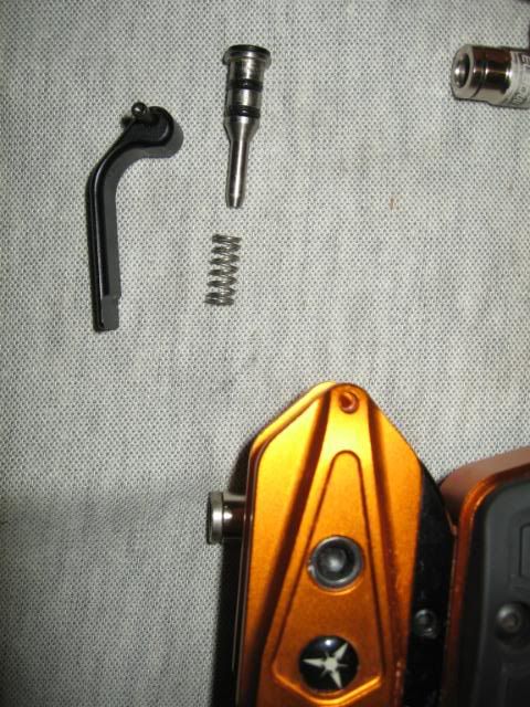
Take note on where the trigger return spring is located in the frame. If you are installing a Magnetic return, this is where you will be super gluing one of the magnets.
Step #4 This picture shows how the trigger sets inside of the trigger frame. At the far end of the trigger directly above where the spring looks like it’s going to touch the trigger, this is where the second magnet will mount for your magnetic return. Make sure that the magnets on both the frame and trigger will repel one another before you super glue the second magnet.

To put back together just reverse the steps.
ENJOY!
Last edited by meMYSELFnI : 10-09-2008 at 10:40 PM.
|
|
|
|
|
10-09-2008, 10:31 PM
|
#12
|
|
|
Useful Knowledge of the Fusion and F8
Here are the Pictures of the Modes for the Fusion V2 board. If you have the V1 board DP allows you to upgrade to the V2 board for a very small price. The F8s modes are identical with the exception of the full auto modes. The last 2 modes that give full auto on the Fusion are ramping modes on the F8. Full auto 15bps is ramping to 15bps 3bps activation. Full auto 25bps is ramping 25bps 3bps activationon the F8.
I posted this one just incase people want to save the image to put inside there markers grip.

This first part is useful info that if done will allow you to have a more smooth cycling bolt and less wear on your marker.
Not all Fusion and F8 need this done, but many do. From the factory the machinists, program, tools, or blueprint made the bolt slot to tight of tolerances. After shooting the Fusion or F8 a common problem happens. The bolt pin hits into the bolt pin slot, mushrooming the metal in the circled areas. When this happens, the bolt gets scratched by dragging on the metal with each shot, and decreases efficiency. Its a minute problem, but one easily fixed. There are several tools that you can use to break off the burrs or even grind them off if you have a steady hand and dremel. Even though these bolt scratches wont hurt the performance of the marker much, it doesnt allow the bolt to cycle as well as it could.
To simply nock off the burrs in the 3 circled areas use a flathead screwdriver. Drag the flathead of the screw driver around the front inside part in the top tube. Youre trying to take off just a little bit of metal. Also, because its in the inside of the tube, it wont be noticeable. The second and third sections dont always need this done. If you get scratches on your ram or bottom of your bolt, you may need to do the same thing where I put the 2 other circles, the one in the middle and on the right.

The next thing I will mention will explain what some of you have asked about. The small hex screws that dont seem to do anything that are located in the front (just under the LPR) and rear of the marker (under the ram cap). These small hex screws are sealing the air passage ways that run through the body. They allow the air to go from the front LPR to the solenoid and then to the ram. IF they didnt drill these tubes, the air would have to be directed through cheap hoses that are more likely to leak. The screws shouldnt ever be removed, loosened, or messed with in any way. The only time to ever remove any of these screws, are unless there is a leak coming from them. If you do need to fix a leak coming from any of these screws I would suggest that you use RED or BLUE loctite. You are able to use RED loctite on these screws since they shouldnt ever need to be removed.
Please read the directions on the loctite before you use it. Allow the loctite to dry according to the directs, before you air up the marker again.
Here are the locations:
The front screw is directly beneath the LPR in the very front of the marker.

There are 2 rear screws located beneath the Ram cap

Then there are 2 internal screws that are located inside the body between the frame and upper body.
The rear screw is shown here.

The Front inside screw is here next to the vertical ASA.

The last thing I will mention is just a trick that Ive been doing for sometime.
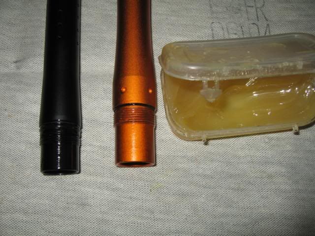
I like to lube my barrel threads on all my barrels with a thick lube. I use Slickhoney since it lasts a long time. This is just to keep the threads looking new and prevent the threads from binding and becoming damaged. I do this with my ASA threads also.
Last edited by meMYSELFnI : 10-09-2008 at 10:41 PM.
|
|
|
|
|
10-09-2008, 10:31 PM
|
#13
|
|
|
Okay all done. I think...
Hopefully DP will help me correct anything that's wrong.
hint hint - parts kit - hint hint
I listed what I could see and the items not included was from research I had done here.
If Brad or someone else from DP could send me the complete info on what's included and of how many, I would appreciate it.
Last edited by meMYSELFnI : 10-09-2008 at 11:27 PM.
|
|
|
|
|
10-09-2008, 10:43 PM
|
#14
|
|
Jason Vitalich Fan #1
Join Date: Feb 2007
Location: Monterey-CA-831
|
holy ****ing batman
|
|
|
|
|
10-09-2008, 10:44 PM
|
#16
|
|
yes means yes
Join Date: Nov 2007
Location: 714
|
iknowrite?
__________________
Please do not forget to leave return feedback :)
|
|
|
|
|
10-10-2008, 12:15 AM
|
#17
|
|
Play paintball
Join Date: Mar 2004
Location: Casper, WY
|
Very very nice bud! Every Fusion owner should thank you for taking the time to do this. I personally appreciate it very much
|
|
|
|
|
10-10-2008, 05:59 AM
|
#18
|
|
Guest
|
This looks great! Thanks for the good work.
|
|
|
|
|
10-10-2008, 06:02 AM
|
#19
|
|
Join Date: Apr 2007
Location: Northeast GA
|
I <3 KIP!
Mucho perfecto!!
REPLACE STICKY NOW
__________________
HeadShot Heroes "Keeping your jersey clean since 2k7"
|
|
|
|
|
10-10-2008, 08:04 AM
|
#20
|
|
Death Dealer
Join Date: Jan 2005
Location: PA
|
Very nice
|
|
|
|
|
10-10-2008, 10:08 AM
|
#21
|
|
Guest
|
Wow that was the best post ever STICKY
|
|
|
|
 Posting Rules
|
You may not post new threads
You may not post replies
You may not post attachments
You may not edit your posts
HTML code is Off
|
|
|
|


 Your Privacy Choices